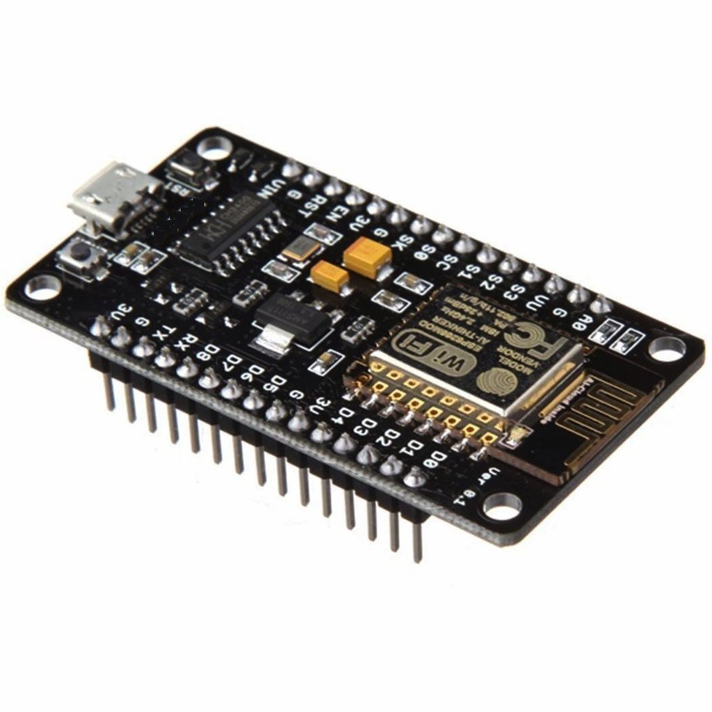
PROJECT: NeoPixel WS2812 WS2812B RGB LED Magic Project
UECIDE software to drive the LED - https://uecide.org/tour
Youtube video for project ideas - WS2812/WS2812B
Youtube video tutorials
Website references & tutorials
https://learn.adafruit.com/adafruit-neopixel-uberguide/the-magic-of-neopixels
Neopixels are about to change - https://blog.particle.io/heads-up-ws2812b-neopixels-are-about-to-change/
Arduino FreeRTOS - https://circuitdigest.com/microcontroller-projects/arduino-freertos-tutorial1-creating-freertos-task-to-blink-led-in-arduino-uno
https://randomnerdtutorials.com/guide-for-ws2812b-addressable-rgb-led-strip-with-arduino/
Some products to reference
Adafruit 64x64 RGB LED Matrix - 2.5mm pitch - https://www.adafruit.com/product/3649
Flexible Matrix 8x32 - https://www.smart-prototyping.com/WS2812B-flexible-LED-matrix-8x32&tracking=591c00a48ed2d
BlinkStick - https://www.blinkstick.com/products/blinkstick-pro
Blink(1) - https://blink1.thingm.com
Fit-statUSB
Adafruit Neopixel Library - Brightness control https://forums.adafruit.com/viewtopic.php?t=41143
Using Blynk App - https://iotdesignpro.com/projects/blynk-controlled-ws2812-neopixel-led-strip-using-esp8266-nodemcu
Things to remember - for #include <Adafruit_NeoPixel.h>
Adafruit_NeoPixel strip(LED_COUNT, LED_PIN, NEO_GRB + NEO_KHZ800);
Note: ensure correct device/part is declared (for NEO_GRBW or NEO_GRB). The data size is different and the outcome will be impacted.
https://learn.adafruit.com/adafruit-neopixel-uberguide/arduino-library-use
pixels.setBrightness(255); //. <— 255 is brightest; 0 is the lowest
pixels.show();
pixels.clear();
There is command to clear all LED, but below code to change color of all LEDs.
for(int i = 0; i < pixels.numpPixels(); i++){
pixels.setPixelColor(i, RedValue, GreenValue, BlueValue);
}
pixels.show();
PROJECT: Humanoid Animatronic eyes
This is a very natural animatronic eyes based on 8x micro hobby eyes. There are some variation of this project with the embedded camera with objection/movement tracking.
STATUS: 3D Parts are printed, but the micro servos I had in stock did not fit. The 10x servos have been ordered (39g micro servos, 4x per eye). Also, glass doll eyes have been order as well. The arrival data is end of July 2020, but I can push forward as soon as the servos arrive.
Next Step: Once the servos arrive, I will assemble the parts & program the servo controller. Once I can get it to move naturally, the next step is to have it controlled by the computers like Raspberry pi which will act as the brain of the robot. I think the natural eyes and hands play a very important part of the humanoid, so I will likely be making various version of these and learn.
Thingiverse site to download the parts
Arduino code repo
Other References (with embedded camera/eyes)
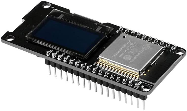
RESEARCH: ESP32/ESP-WROOM-32 Development Board with 0.96" OLED Display - by MELIFE
This is a nice ESP32 development board with a built-in 0.96” OLED display. ESP32 is 10x faster than the 8bit Arduino Uno and has dual core 160 MHz processor and onboard WiFi and Bluetooth.
Development board is based on ESP-WROOM-32
0.96” OLED display; 2.4GHz Dual mode WiFi; Low power Bluetooth
Note: This is a small compacted dev board - however the footprint is slightly wider than the standard ESP8266. This causes problem with the standard breadboard not able to support its wider size. There are various breadboard hacks to support the usage with the ESP32 (e.g. I like to remove the power rails on the both side of the breadboard and moving it inward which keeps the overall footprint of the breadboard while being able to support the ESP32)
Description
References - from the user feedbacks and questions
External vin voltage (external power) - voltage for USB is 5V; voltage for the external power supply is 3.3V
GPIO 0 - pin 0 may not have been brought out.
Reference for workaround : https://randomnerdtutorials.com/esp32-pinout-reference-gpios/
To upload from the Arduino IDE
oppose to the ESP8266, to upload, you need to keep the “Boot/Flash” button pressed until the upload begins, then release it. Otherwise, the upload fails. (NOTE: this may be unique to this board compared to other ESP32 - hold down the boot button before uploading arduino sketch & once the ide connects, release button)
Select the Arduino board as “generic ESP32 dev module” in the Arduino IDE. Example of the IDE 1.8.5
ESP Dev Module
Flash Mode: QIO (may need to use DIO, see below)
some users had to set it to DIO in order to get the board to boot; Arduino 1.8.9
Flash mode QIO consistently resulted in a core panic / boot loop while writing Grbl_Esp32 to the board with Arduino IDE 1.8.10. https://www.esp32.com/viewtopic.php?t=1250
On Mac OS, also need https://www.silabs.com/products/development-tools/software/usb-to-uart-bridge-vcp-drivers to get `/dev/cu.SLAB_USBtoUART`.
CPU frequency: 240MHz (WiFi/BT)
PSRAM: disabled
Flash Size: 4MB (32Mb)
Partition scheme: default 4MB with spiffs (1.2MB app/1.5MB SPIFFS)
Flash frequency: 80MHz
Upload speed:921600
Core debug level: none
Port: depends on your PC (COM4 for mine)
Trouble getting the OLED display to work
Ended up finding the solution in the comments of the HiLetgo version of this board. Copy/Paste:
To initialize the OLED display, use: "SSD1306 display (0x3c, 5, 4)
The default D3 needs to be changed to 5, and the D5 needs to be changed to 4."
screenshot - Screen+Shot+2020-05-24+at+7.05.06+PM.png
This was using an example sketch in Arduino IDE.
MacOS users may have a lot of trouble getting the computer to see it as a serial device even after installing the new & legacy SLI Labs USB to UART drivers, and trying various USB-A to C cables and adapters. You may try using a USB hub instead of a straight cable or adapter and/or connecting the board to the Macbook through a USB-C dock
Pin Mapping - NOTE: This version of the ESP32 board may have different pin mapping than the standard NodeMCU-32S ESP32 dev board. This means your Eagle footprint and wiring diagrams must be adjusted. (NOTE: the ESP32 dev boards seem to come in 2 varieties: 36 pin and 30 pins (this board comes with 30pins)
PROS
Pin Labels are on top of the board (vs NodeMCU-32S boards have the labels on the bottom of the board, so when the module is plugged into a breadboard, you cannot see the labels)
cheaper than the NodeMCU-32S dev modules
Genuine Espressif ESP32 is like Cadillac among cars (beautifully designed but costing twice as much as MELIFE)
it is good having already built in 0.96 OLED
Wemos D1 R32 has slower MCU and also slower USB to UART bridge (CH340G instead of desirable CP2102). It works but beginner will stumble on proper settings for MCU clock, and upload speed (they are slower than defaults for ESP32 boards).
Recommended Book: Learn ESP32 with Arduino IDE by Rui Santos and Sara Santos
All projects presented works with MELIFE perfectly. Code is clearly explained. The book will save you a lot of time and frustration browsing Internet for solution answers.
Also, it is an advantage having more ESP32 modules: you can work in parallel on more than one project. Beside, some projects need two modules (on picture I am presenting one MELIFE module sending temperature and humidity from sensor HDT11 using bluetooth to other MELIFE module with OLED display).
The board is based on the Wemos LOLIN32 model and has an OLED attached. The OLED is written using the i2c protocol by any of the commonly available Internet libraries for the Arduino IDE and ESP32.
The web site for Random Nerd Tutorials has a pinout and example code. I pay to be a member of RNT and recommend them for easy to follow tutorials. Many of their guides don’t require membership.
The best part of this board is the already attached OLED which is stark white on black for high contrast. It is a common 128 x 64 pixel size which allows both text and graphics. I was able to interface a 3 pin Temp / Humidity sensor and have accessed the National Time protocol features of the NTP using another common library. I like that the most often used pins are all on one side of the board.
The only thing I dislike is the BOOT and RESET buttons are both on the reverse of the board so if you plug it into a breadboard or solder into a circuit, it is difficult to access the buttons for programming.
On my PC and USB interface, I have to press & hold the BOOT button until the loader says it has contact with the board.
USB cable issues
Not all USB cables are "data" cables … some have just the power wires connected ("charging cables").
Watch out for USB charger cables that do not have data pins. Multiple times this got me, I spent hours trying to fix a communication issue caused by a non-data cable
WiFi stability
I have had some issues with WIFI stability. I have an application where I want it to stay connected (and re-connect) when needed. However, it only seems to re-connect once. It will remain connected for a few weeks but eventually I'll have to cycle power. I have had to program in an auto re-boot everyday to get around the WIFI issue.
Espruino / Javascript firmware
Try out the Espruino / Javascript firmware if you don't have a lot of microcontroller programming experience. (NOTE: It now also supports MicroPython as well)
I first tired flashing with Python and was able to get a simple project working quickly. However, I have switched over to Espurino which works with Javascript. Espruino seems to handle repetitive timed tasks better with it's setInterval and setTimeout functions. The best part of Esprunio is that I can quickly send a single line of code to the the Terminal and see how it works without compiling an entire C program.
The Espressif IDE is *MUCH MUCH* better than the Arduino. I do highly recommend. It is a “real” full-fledged professional RTOS. All the stuff I spent weeks trying to duxct-take together in Arduino development environment just worked out-of-the box in Espressif.
Other references
https://makeradvisor.com/esp32-development-boards-review-comparison/
MELIFE w/o OLED, 2 pack - https://www.amazon.com/MELIFE-Development-Dual-Mode-Microcontroller-Integrated/dp/B07Q576VWZ/ref=sr_1_fkmr0_1?dchild=1&keywords=MELIFE+OLED+ESP-WROOM-32+ESP32&qid=1588458418&s=digital-text&sr=8-1-fkmr0
Other resources for MELIFE ESP32 w/o OLED
If it cann't get bluetooth working?
Using Node32s as the Board selection. To reference GPIO pins in code use just the number, for example "digitalWrite(13, HIGH)" sets GPIO13 high.
The built-in LED to GPIO2.
RESEARCH: NVIDIA Jetson Nano Developer Kit & Jetson Xavier NX
Jetson Nano is a newly released (as of 2020) AI/ML processing small form factor computer. More capable versions exist such as Xavier shown on the video above.
Getting Started with the Jetson Nano
https://developer.nvidia.com/embedded/learn/get-started-jetson-nano-devkit
https://developer.nvidia.com/embedded/jetson-nano-developer-kit
ROS on Jetson Nano
https://www.stereolabs.com/blog/ros-and-nvidia-jetson-nano/
Jetson Nano Case
https://www.waveshare.com/wiki/Jetson_Nano_Case_(C)
NVIDIA Jetson Xavier NX - simple review
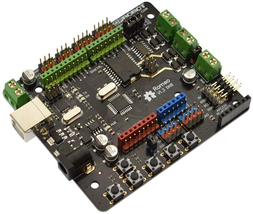
RESEARCH: DFRobot Romeo - Robot Control Board with Motor Driver based on Arduino
Romeo is an All-in-One Arduino compatible microcontroller especially designed for robotics applications. Its All-in-One design allows for smaller footprint by eliminating the need for additional motor drivers. This may be very useful in the implementation with a smaller rover robots that has limited space within the chassis. On-board buttons maybe very useful as I/O for driving menu functions on a small robot.
Based on Arduino Uno & two 2A DC motor drivers & socket for bluetooth - allows for a robotic project without a need for additional DC motor driver and bluetooth shield
Integrated sensor shield - access to Arduino-compatible shields with additional sensors
Arduino open source platform - access to existing Arduino open source codes
Specifications
This version of the board is based on ATmega328 microcontroller.
Analog inputs x8, PWM x6; I2C x3, 32 KB memory
Note: this version of the board is using a large USB port found in the Arduino Uno
v2.0 board supports Micro USB; 12x analog inputs; 7x PWM
Description (version 1.3 - based on Arduino Uno)
Description (version 2.0 - based on Arduino Leonardo)
https://www.amazon.com/dp/B00C9NWTQE/ref=emc_b_5_t
Product Wiki
https://wiki.dfrobot.com/DFRduino_Romeo-All_in_one_Controller_V1.1_SKU_DFR0004_
Additional References -user review of the v2.0
PRO: Row of three male pins for each female pin from D0 through D13 - makes it very easy to plug female connection wires into the board
PRO: Six programmable buttons and external power for the servo motors
PRO: Built in motor control - uses only two pins per motor to manage
Work Around: Lacks customer support - contact directly to the RF Robot via email and/or forum
User Choice: For the field use, Micro USB may be too fragile - however, Micro USB offer smaller footprint and common cable
Word Around: There may be an issue with uploading the sketch due to flaky programmer - (this issue may not exist in the v1.3 board)
CON: Pins used to drive the motor clash with the pins used to power the DF Robot LCD Keyboard Shield - not able to use the shield to display data on the status of the system (may not be an issue for the v1.3 board and/or work around)
RESEARCH: Best Raspberry Pi 4B Case (Optimized for Makers and Hackers)
The new Raspberry Pi 4B was introduced in June 2019 with the choices of RAM of 1GB, 2GB, and 4GB. As of March 2020, 4GB and 2GB models were a runaway success despite of relatively higher price point compared to the previous $35 price point for a Rpi. Rpi 4B 1GB model was the entry point, but it did not show a clear distinction between the previous Rpi 3B+ model which has slightly slower CPU and same size RAM (well.. actually, 4B model had Gigabit ethernet which was big). Later Rpi 4B 1GB model was discontinued and the price point of the 2GB model was lowered to $35 as a new entry point.
Due to the faster CPU (and overclock option), faster ethernet, and more RAM, the Rpi 4B models were reported to have overheating issues. I wanted to find a rugged case that offered passive cooling as well an active fan cooling option as my use case for these 4B models require more computation. Following are a few cases that I ordered from the Amazon.
iUniker Raspberry Pi 4 Case, CNC Metal Case Aluminium Alloy, Cooling Heatsink for Raspberry Pi 4 Model/Pi 4
https://www.amazon.com/gp/product/B07ZQ2F6DB/ref=ppx_yo_dt_b_asin_title_o08_s00?ie=UTF8&psc=1
PROS: A solid/heavy metal case that enclose the entire Rpi unit. Kind of feels like a solid bar of soap. Passive cooling works well for my Rpi 4B 1GB model running light tasks.
CONS: No direct access to the GPIO pins without opening the case (however it does have openings to run cables out of the case). Passive cooling might not be enough for computational intensive tasks that will create lots of heat over a long duration.
Conclusion: I really like the solid feel of this case with no moving parts to break as my use case will be to carry it around in my project case to drive my electronic projects/demos.
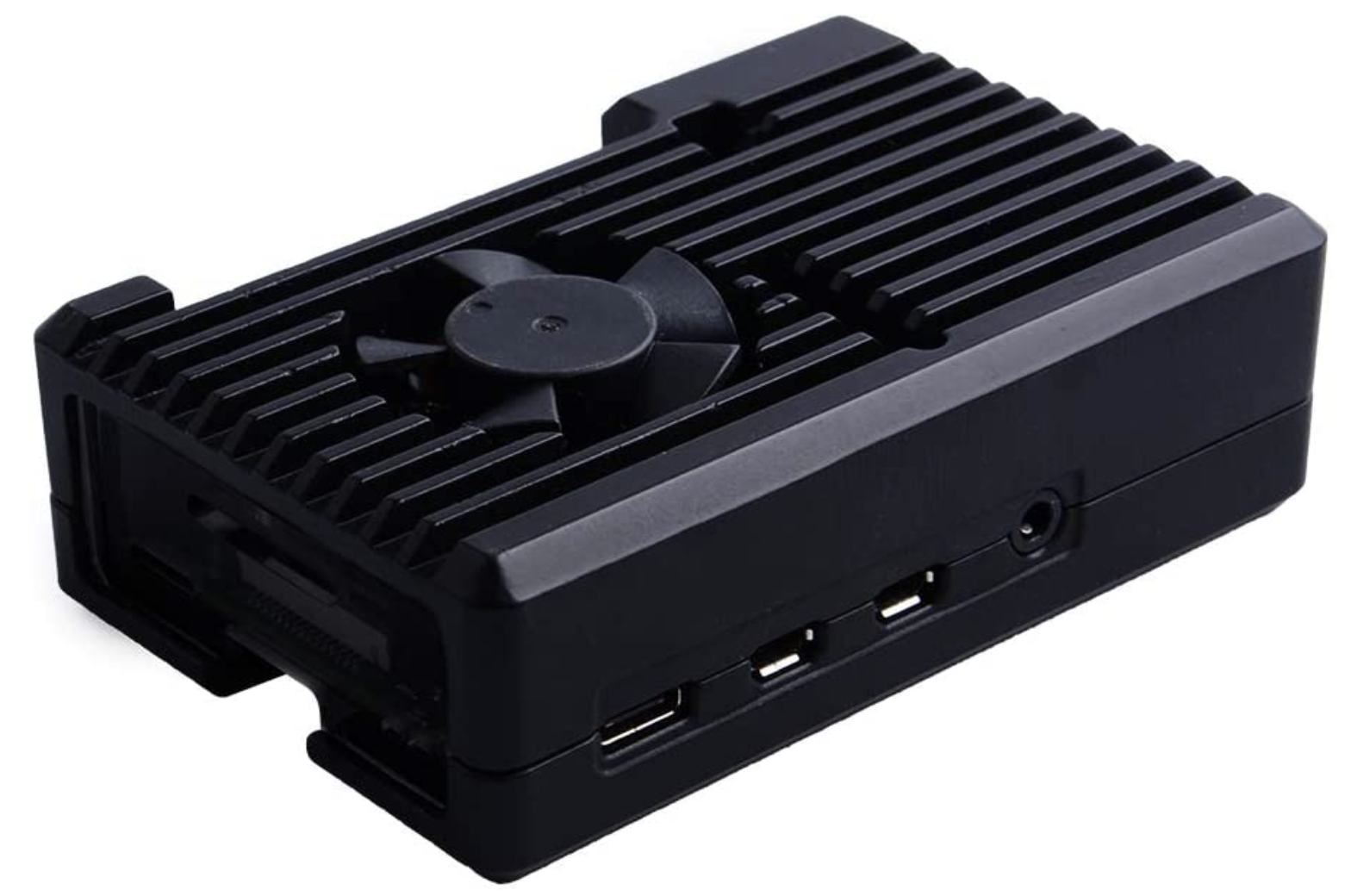
GeeekPi Raspberry Pi 4 Model B Armor Case with Fan, Passive Aluminum Alloy Case with Cooling Fan (3510 Fan)
https://www.amazon.com/gp/product/B083XV78RD/ref=ppx_yo_dt_b_asin_title_o08_s01?ie=UTF8&psc=1
PROS: A solid/heavy metal case with a fan to provide active cooling. This unit feels like the passive cooling unit described above. The fan was very quiet and the case remained cool after running YouTube for an hour on my 2GB unit. GPIO pins are accessible for the frequent use.
CONS: No cover or protection for the accessible GPIO pins.
Conclusion: I really like this solid case that provides both passive and active cooling. Having access to the GPIO pins make it a great unit to carry around to drive my electronic projects and demos that requires GPIO access. If I have to pick one for portable use, this will be my pick for my use case.
Argon NEO Raspberry Pi 4 Model B Heatsink Case, GPIO and PoE Pins are Accessible
https://www.amazon.com/gp/product/B07WMG27T7/ref=ppx_yo_dt_b_asin_title_o02_s00?ie=UTF8&psc=1
PROS: WIP - Awaiting delivery
CONS: WIP - Awaiting delivery
Conclusion: WIP - This one is very stylish passive cooling case which provide access to the GPIO pins. Compared to the first one which has the fins (heat sink), this one may not be as effective in cooling the unit. I will have to try it out when it arrives.
Argon ONE Raspberry Pi 4 Model B Case with Cooling Fan and Power Button
https://www.amazon.com/gp/product/B07WP8WC3V/ref=ppx_yo_dt_b_asin_title_o05_s00?ie=UTF8&psc=1
PROS: WIP - Awaiting delivery
CONS: WIP - Awaiting delivery
Conclusion: WIP - This one is highly rated due to the stylish case with active cooling fan, access to the GPIO fan, and Rpi In/Out ports all routed to the back of the unit. I plan to house my 4GB unit that will stay at my lab, so the form factor works well. I will have to try it out once it arrives.
WORK IN PROGRESS BELOW—————————————————————
Workaround for a Raspberry Pi not working on some HDMI (e.g. connecting to Samsung TV)
Note for Raspberry Pi4B
because Rpi 4B now has two HDMI ports, HDMI commands now can be applied to either or both ports. Syntax is <command>:<port>
Port 0 is default (if no port is specified, the default is set)
Once your uncomment the #hdmi_safe=1 (to have the Rpi’s HDMI to work with most types of displays), you may have the situation of the picture from both port 0 and 1, but sound only from the port 0. This maybe a bug that is not configured to apply to sound in port 1 (which is new as of Rpi 4B).
Additional reference
Issue with Raspberry Pi 4B connecting to wifi 5Ghz
I was able to connect to 2.4 GHz with no issue, but 5GHz will not connect my Rpi even though I was able to see the SSID. After messing around, I tried to re-image the OS to the SD card again and re-installed the OS.
I was using Raspbian OS Buster - I was being careful with the initial setup especially with the wifi configuration (only configured using 5GHz). It did not see any SSID during the initial setup, but was able to manually select the SSID (it did see both 2.4 & 5GHz) and enter the passphrase. Initially, I had issue with the connection being made and getting disconnected. After a while, the connection was maintained.
As the 5 GHz range is shorter than 2.4 GHz, I am assuming the issue has to do with the 5 GHz channel with my router. The situation probably was worsen with the heavy metal ‘passive + fan cooling’ case I have on this Rpi 4B with 2GB. I will have to see if this issue returns.
Safe Shutdown button
I never really liked using software/script based shutdown button due to the instability/reliability of its functionality. However, I wanted to have this simple shutdown button for the prototypes I will be building that will be used by many users.
PROJECT: RetroPie - Retro-Gaming on the Raspberry Pi (2020 Update)
WORK IN PROGRESS
The update to the new RetroPie OS and the NESPi Case+ is complete
However, new RetroPie OS based on Raspbian Buster (beta) just got release - So I will have to test the new version
PROJECT: 2020 Update of the RetroPie - Retro-gaming System
Case used: NESPi Case+ (note: + model supports power shutdown)
Gamepad: Logitech Gamepad F310
RetroPie OS: 2017 version was outdated and the lastest March 2020 version was installed.
Coming Soon : Lessons learned for the install etc (+ Buster based OS as well)
Retropie ROM
Research - Raspberry Pi project
Raspberry Pi Projects
Raspberry Pi Add-on boards
Astro-Pi
https://www.raspberrypi.org/blog/buy-the-sense-hat-as-seen-in-space/
https://astropicase.com/product/replica-astropi-case-standard-kit/
https://www.raspberrypi.org/blog/how-you-an-adult-take-part-in-european-astro-pi-challenge/
Raspberry Pi vs Beaglebone
Raspberry Pi 3B+ vs 3B
MASTER CLASS: Mr. Masahiko Yamaguchi (aka Dr. Guero)
Mr. Masahiko Yamaguchi at the 2011 International Robot Exhibition, Tokyo Japan
“I am interested in artificial intelligence, and in that context, I think intelligence and skills have equal value. So my purpose in creating this robot was to pursue intelligence from the skills perspective.”
One of my heroes of the Bipedal Humanoid is Mr. Masahiko Yamaguchi (aka Dr. Guero, Youtube). Hi’s research on balancing robot is simply amazing. Access to his work by the English speaking audience is only limited through the awful internet translation services. As the modest nature of a Japanese culture and introverted temperament of a technologist, I doubt he will ever PR himself on the internet. I wanted to dedicate this page to share some of the greatest work done by Mr. Masahiko Yamaguchi.
Blog in Japanese - http://ai2001.ifdef.jp
Youtube channel - https://www.youtube.com/user/DrGuero2001
Tamagawa Seiki demo at 2011 iRex, Tokyo Japan - https://youtu.be/mT3vfSQePcs
Demo of the Stilts Robot, 5th ROBO-ONE on PC - https://youtu.be/B5T2httvnCk
Who is Dr. Guero?
Name: Masahiko Yamaguchi
Current Residence: Shizuoka, Japan
Nickname: Dr. Guero (The nickname was given by his wife who is a big fan of popular Japanese anime Dragon Ball. Dr. Guero is an evil genius robot inventor who was the master mind behind the RR army. Perhaps it is a fitting nickname since the husband is alway working on robots and is rarely available to help with the housework.)
Significance of 2001 reference in your ID? - It is a reference to the favorite move “2001: Space Odyssey”
Robotics Research:
Currently being pursued as an independent research. I wanted to work on the full-size humanoid or a robot that can be deployed to a real work environment such as a robot to operate in the Fukushima nuclear disaster site. Independent researchers have various difficulties including micro budget usually funded by themselves, and the limitation of equipments/tools and certain skills to build the robot. For this reason, the release of a successful robots are far and far between (based on a forum post in 2013).
Limitation of small humanoid robots:
Characteristics of the servos used in the robot plays a big part; difficult to calculate exact tolerances level from the movements; difficult to process calculations of the mechanical motions of a rapid movement such as dynamic walking
Why focusing on the Bipedal Humanoid?
The approach of the bipedal humanoid requires pursuit of rationality and enhanced logical understanding of human which allows us to develop more useful robots
Robotics is a convergence of various technical disciplines (electrical, mechanical, and software)
My goal is to get to the AI via the use of robotics (based on the forum post in 2015).
Thoughts on consciousness
I think the brain contains something that is "non-computational" which cannot be replaced by symbolic logic.
Work In Progress - Translation of the Dr. Guero Blog
Translation of the main Blog page (done - button/link above)
Translation of the subpages/detail pages (started, but it will take a long time due to the complexity of the topics and the expertise required to understand the material)
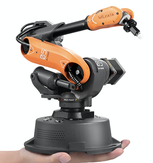
RESEARCH: Mirobot Robot Arm
Mirobot is a miniature highly accurate robotic arm that was launched via the KickStarter in 2020. As the industrial robots such as KUKA is normally not accessible to most people, Mirobot fill the need for a replica for personal use for education and development.
More information to follow as the project backers are starting to receive the robots.
WIP: Motion Follow Animatronics Eyes
Instructable article - https://www.instructables.com/id/Eye-Animatronics/
Thingiverse - Animatronic mini Eye module - https://www.thingiverse.com/thing:2668124
Thingiverse - Animatronic Head full version - https://www.thingiverse.com/thing:3414319
RESEARCH: Robotis Dynamixel Smart Servos
Dynamixel Smart Servos
Dynamixel Comparison - https://www.generationrobots.com/blog/en/how-to-choose-the-right-dynamixel-servomotor/
Robotis e-manuel - http://emanual.robotis.com
Dynamixel AX Series comparison - https://www.robotis.us/ax-series/
Dynamixel MX Series comparison - https://www.robotis.us/mx-series/
MX-64
MX-106
Other
Dynamixel XL-320 (used for Darwin-Mini robot) - http://www.robotis.us/dynamixel-xl-320/
Dynamixel RX Series - discounted
RESEARCH: Interbotix PincherX 150 Robot Arm
Interbotix PincherX 150 Robot Arm
Uses 8x Dynamixel XL430-W250-T to achieve 5 DOF + 360 degrees of rotation.
45cm reach (90cm total span) with 5mm accuracy
RSO support
https://www.trossenrobotics.com/pincherx-150-robot-arm.aspx
Dynamixel XL430-W250-T Smart Servo Motor
Offer high resolution of 4096 positions and user definable PID parameters
Temperature monitoring, positional feedback, as well as voltage levels, load, and compliance settings are user accessible as well
https://www.trossenrobotics.com/dynamixel-xl430-w250-t.aspx
Related resources
Ubiquity – VM image + Rpi image
https://downloads.ubiquityrobotics.com/
Install ROS on Ubuntu – using Robotis script + Install on Raspbian Jessie
https://acslaboratory.github.io/ros/kinetic-ros-installation-guide/
GitHub - X-Series - ROS Stack
https://github.com/Interbotix/interbotix_ros_arms
Github - PhantomX Pincher Mk3 Arm
RESEARCH: Annin Robotics AR2 & AR3 6 axis Robot Arm
Main Website - anninrobotics.com
Blog - https://www.anninrobotics.com/blog
Forum - https://www.anninrobotics.com/forum
Tutorials - https://www.anninrobotics.com/tutorials
Download & Manuals - https://www.anninrobotics.com/downloads
Robot Kits - https://www.anninrobotics.com/robot-kits
PROJECT: INNFOS GLUON - Modular Desktop Robotic Arm (KickStarter - SUSPENDED)
Innfos Gluon - 6DOF
FINAL UPDATE:
I bid on this Kick Starter project to help me with a robot arm research project.
I’ve really liked the build quality and the modularity of the robot despite the lack of availability of the SW tooling.
This Kick Starter project ended up getting cancelled. All the backers got our money back, but I had to also cancel my Gluon Robot Arm research project.
GLUON is an innovative creation. This robotic arm can perform much more complicated actions without being bulky and expensive. INNFOS integrated motor, drive, encoder and reducer in an all-in-one design jazzed-up actuator that created GLUON. The smart compliant actuator is called INNFOS SCA that breakthroughs the old limits of service robotic industry.
KickStarter Link - https://www.kickstarter.com/projects/1383636492/the-smallest-servomotor-robotic-arm?ref=discovery&term=robot
Gluon 6-Axis | Early Bird - Pledge $759 or more
Get your Gluon 6-Axis Robotic Arm DIY Kit at a better price! Save $540 off the retail price.
Funding Close December 26, 2019
Includes: 6-Axis Robotic Arm DIY Kit
Estimated Delivery: Jun 2020
INNFOS GITHUB PAGE
Kickstarter Update: As of January 2020, the project was suspended & the backing was refunded
Robot Arm - PROJECT VISION & GOALS
VISION
TBD - No clear vision at this time. Research Phase.
GOALS - 2020 (planned to use Innfos Gluon 6 DOF Robot Arm)
Suspended - Robot Arm use case in production
Suspended - ROS implementation of Robotic Arm
Suspended - Simulation & Machine Learning use case
Suspended - Apply Inverse Kinematics - Robot Arm Frame
GOALS - 2021
Completed - Back to the basics - Simple Arduino 4DOF Acrylic Robot Arm Kit
WIP - Implement advanced functionalities to the 4DOF Robot Arm
RESEARCH: ESP8266 & ESP32
For the maker community as of 2019, ESP8266 and ESP32 are most commonly used in place of the Arduino. The main reason for the popularity includes small form factor, cheaper price point, support for Arduino IDE for programming, and built in Wifi. These models are produced by the Espressif Systems in Shanghai, China.
ESP8266 - Released in 2014 - https://en.wikipedia.org/wiki/ESP8266
CPU: 80 MHz (default) or 160 MHz (single core 32-bit) processor
Memory: 32 KiB (80 KiB user data)
Input: 16 GPIO pins
Comm: 802.11 wifi
CONS - One of the major drawback is the lack of security - details WIP
ESP32 - Released in 2016 - https://en.wikipedia.org/wiki/ESP32
CPU: 160 or 240 MHz (dual core 32-bit) processor
Memory: 520KiB SRAM
Input: TBD (need to confirm)
Comm: 802.11 b/g/n Wifi; Bluetooth v4.2
CONS - Some of the older codes written for 8266 may not run on the ESP32. However, I would initiate new projects based on the ESP32.
WORK IN PROGRESS BELOW———————————————-
ESP32 vs ESP8266 - Pros and Cons
https://makeradvisor.com/esp32-vs-esp8266/
ESP32 Pinout Ref
https://randomnerdtutorials.com/esp32-pinout-reference-gpios/
ESP8266 Pinout Ref
https://randomnerdtutorials.com/esp8266-pinout-reference-gpios/
Banggood - description
Andy’s blog
http://www.areresearch.net/2018/02/the-all-you-can-possibly-want-esp8266.html#
ESP8266 Deauther 2.0
https://github.com/spacehuhn/esp8266_deauther/blob/master/README.md
https://www.youtube.com/watch?v=elKXLAs3zII
https://github.com/spacehuhn/esp8266_deauther/wiki/Installation#flashing-the-firmware-bin-file
Spitfire EV Project - Ending the body restoration phase
The blog post on TechnologyX2 details the progress of the Spitfire EV Project, focusing on the completion of the major body restoration phase. The author describes the meticulous process of removing layers of old paint, repairing dents, and applying a protective epoxy primer/sealer to the bare metal. This phase sets the stage for future work on the car's electronics and internals. The post emphasizes the importance of taking time in restoration to learn and acquire skills, along with the enjoyment of sourcing original replacement parts. The next steps include focusing on the car's electrical system and integrating both digital and classic elements into the design.
For more detailed information, you can read the full blog post [here](https://www.technologyx2.com/blog_hightech/2019/10/8/spitfire-ev-project-ending-the-major-restoration-phase).
With the weather getting a bit cooler, I’ve pushed forward and made a progress with the body work. Several layers of old paints scraped down to the bare metal, many hours of hammer and dolly work, and stud welder to pull out the nasty dents. Moving slowly and doing a good job here will pay off when I get to the final phase to lay down the color and protective coats.
Down to the bare metal and the hardware removed.
A few more spots to sand off.
Polished metal signify the end is near.
I think it is really important for the bare metal to get a good protective seal with the Epoxy Primer/Sealer. It seals the work that is performed between the job for the weekend warriors. As for me, it will serve as a nice protective layer while I work on the ‘electronics/internals’ of the car, allowing me to come back next spring/summer to work on it again and finish it off with the filler and final color paint.
Look. Finally the car is a single color…. Almost.
Many of hours of hammer and dolly paid off.
Spitfire is such a beauty. As I have only a few more spots left to finish, I am now moving to the second phase of the project. I can now shift my focus to the re-designing of the “Electrics” side of the vehicle. The real fun begins.
By the way, I have been slowly acquiring replacement parts which will be needed when I get to the final phase of the project. I think the secret to a successful restoration project is to go slow enough for you to learn things along the way and do many of the work yourself. Not only does it keep the project within budget, but the skills acquired can go a long way. Also, hunting for the original replacements parts are a major part of the fun.
I plan to install a digital screen for monitoring the ‘electric’ part of the car, but having these analog meters are just a look I can’t go without.
You won’t believe how much I paid for these rear lights. Finding these gems are definitely a part of the fun.
And up course, I had to have these original gear shift handles.
