PROJECT: NeoPixel WS2812 WS2812B RGB LED Magic Project
UECIDE software to drive the LED - https://uecide.org/tour
Youtube video for project ideas - WS2812/WS2812B
Youtube video tutorials
Website references & tutorials
https://learn.adafruit.com/adafruit-neopixel-uberguide/the-magic-of-neopixels
Neopixels are about to change - https://blog.particle.io/heads-up-ws2812b-neopixels-are-about-to-change/
Arduino FreeRTOS - https://circuitdigest.com/microcontroller-projects/arduino-freertos-tutorial1-creating-freertos-task-to-blink-led-in-arduino-uno
https://randomnerdtutorials.com/guide-for-ws2812b-addressable-rgb-led-strip-with-arduino/
Some products to reference
Adafruit 64x64 RGB LED Matrix - 2.5mm pitch - https://www.adafruit.com/product/3649
Flexible Matrix 8x32 - https://www.smart-prototyping.com/WS2812B-flexible-LED-matrix-8x32&tracking=591c00a48ed2d
BlinkStick - https://www.blinkstick.com/products/blinkstick-pro
Blink(1) - https://blink1.thingm.com
Fit-statUSB
Adafruit Neopixel Library - Brightness control https://forums.adafruit.com/viewtopic.php?t=41143
Using Blynk App - https://iotdesignpro.com/projects/blynk-controlled-ws2812-neopixel-led-strip-using-esp8266-nodemcu
Things to remember - for #include <Adafruit_NeoPixel.h>
Adafruit_NeoPixel strip(LED_COUNT, LED_PIN, NEO_GRB + NEO_KHZ800);
Note: ensure correct device/part is declared (for NEO_GRBW or NEO_GRB). The data size is different and the outcome will be impacted.
https://learn.adafruit.com/adafruit-neopixel-uberguide/arduino-library-use
pixels.setBrightness(255); //. <— 255 is brightest; 0 is the lowest
pixels.show();
pixels.clear();
There is command to clear all LED, but below code to change color of all LEDs.
for(int i = 0; i < pixels.numpPixels(); i++){
pixels.setPixelColor(i, RedValue, GreenValue, BlueValue);
}
pixels.show();
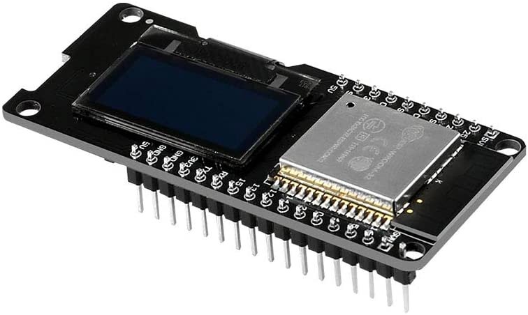
RESEARCH: ESP32/ESP-WROOM-32 Development Board with 0.96" OLED Display - by MELIFE
This is a nice ESP32 development board with a built-in 0.96” OLED display. ESP32 is 10x faster than the 8bit Arduino Uno and has dual core 160 MHz processor and onboard WiFi and Bluetooth.
Development board is based on ESP-WROOM-32
0.96” OLED display; 2.4GHz Dual mode WiFi; Low power Bluetooth
Note: This is a small compacted dev board - however the footprint is slightly wider than the standard ESP8266. This causes problem with the standard breadboard not able to support its wider size. There are various breadboard hacks to support the usage with the ESP32 (e.g. I like to remove the power rails on the both side of the breadboard and moving it inward which keeps the overall footprint of the breadboard while being able to support the ESP32)
Description
References - from the user feedbacks and questions
External vin voltage (external power) - voltage for USB is 5V; voltage for the external power supply is 3.3V
GPIO 0 - pin 0 may not have been brought out.
Reference for workaround : https://randomnerdtutorials.com/esp32-pinout-reference-gpios/
To upload from the Arduino IDE
oppose to the ESP8266, to upload, you need to keep the “Boot/Flash” button pressed until the upload begins, then release it. Otherwise, the upload fails. (NOTE: this may be unique to this board compared to other ESP32 - hold down the boot button before uploading arduino sketch & once the ide connects, release button)
Select the Arduino board as “generic ESP32 dev module” in the Arduino IDE. Example of the IDE 1.8.5
ESP Dev Module
Flash Mode: QIO (may need to use DIO, see below)
some users had to set it to DIO in order to get the board to boot; Arduino 1.8.9
Flash mode QIO consistently resulted in a core panic / boot loop while writing Grbl_Esp32 to the board with Arduino IDE 1.8.10. https://www.esp32.com/viewtopic.php?t=1250
On Mac OS, also need https://www.silabs.com/products/development-tools/software/usb-to-uart-bridge-vcp-drivers to get `/dev/cu.SLAB_USBtoUART`.
CPU frequency: 240MHz (WiFi/BT)
PSRAM: disabled
Flash Size: 4MB (32Mb)
Partition scheme: default 4MB with spiffs (1.2MB app/1.5MB SPIFFS)
Flash frequency: 80MHz
Upload speed:921600
Core debug level: none
Port: depends on your PC (COM4 for mine)
Trouble getting the OLED display to work
Ended up finding the solution in the comments of the HiLetgo version of this board. Copy/Paste:
To initialize the OLED display, use: "SSD1306 display (0x3c, 5, 4)
The default D3 needs to be changed to 5, and the D5 needs to be changed to 4."
screenshot - Screen+Shot+2020-05-24+at+7.05.06+PM.png
This was using an example sketch in Arduino IDE.
MacOS users may have a lot of trouble getting the computer to see it as a serial device even after installing the new & legacy SLI Labs USB to UART drivers, and trying various USB-A to C cables and adapters. You may try using a USB hub instead of a straight cable or adapter and/or connecting the board to the Macbook through a USB-C dock
Pin Mapping - NOTE: This version of the ESP32 board may have different pin mapping than the standard NodeMCU-32S ESP32 dev board. This means your Eagle footprint and wiring diagrams must be adjusted. (NOTE: the ESP32 dev boards seem to come in 2 varieties: 36 pin and 30 pins (this board comes with 30pins)
PROS
Pin Labels are on top of the board (vs NodeMCU-32S boards have the labels on the bottom of the board, so when the module is plugged into a breadboard, you cannot see the labels)
cheaper than the NodeMCU-32S dev modules
Genuine Espressif ESP32 is like Cadillac among cars (beautifully designed but costing twice as much as MELIFE)
it is good having already built in 0.96 OLED
Wemos D1 R32 has slower MCU and also slower USB to UART bridge (CH340G instead of desirable CP2102). It works but beginner will stumble on proper settings for MCU clock, and upload speed (they are slower than defaults for ESP32 boards).
Recommended Book: Learn ESP32 with Arduino IDE by Rui Santos and Sara Santos
All projects presented works with MELIFE perfectly. Code is clearly explained. The book will save you a lot of time and frustration browsing Internet for solution answers.
Also, it is an advantage having more ESP32 modules: you can work in parallel on more than one project. Beside, some projects need two modules (on picture I am presenting one MELIFE module sending temperature and humidity from sensor HDT11 using bluetooth to other MELIFE module with OLED display).
The board is based on the Wemos LOLIN32 model and has an OLED attached. The OLED is written using the i2c protocol by any of the commonly available Internet libraries for the Arduino IDE and ESP32.
The web site for Random Nerd Tutorials has a pinout and example code. I pay to be a member of RNT and recommend them for easy to follow tutorials. Many of their guides don’t require membership.
The best part of this board is the already attached OLED which is stark white on black for high contrast. It is a common 128 x 64 pixel size which allows both text and graphics. I was able to interface a 3 pin Temp / Humidity sensor and have accessed the National Time protocol features of the NTP using another common library. I like that the most often used pins are all on one side of the board.
The only thing I dislike is the BOOT and RESET buttons are both on the reverse of the board so if you plug it into a breadboard or solder into a circuit, it is difficult to access the buttons for programming.
On my PC and USB interface, I have to press & hold the BOOT button until the loader says it has contact with the board.
USB cable issues
Not all USB cables are "data" cables … some have just the power wires connected ("charging cables").
Watch out for USB charger cables that do not have data pins. Multiple times this got me, I spent hours trying to fix a communication issue caused by a non-data cable
WiFi stability
I have had some issues with WIFI stability. I have an application where I want it to stay connected (and re-connect) when needed. However, it only seems to re-connect once. It will remain connected for a few weeks but eventually I'll have to cycle power. I have had to program in an auto re-boot everyday to get around the WIFI issue.
Espruino / Javascript firmware
Try out the Espruino / Javascript firmware if you don't have a lot of microcontroller programming experience. (NOTE: It now also supports MicroPython as well)
I first tired flashing with Python and was able to get a simple project working quickly. However, I have switched over to Espurino which works with Javascript. Espruino seems to handle repetitive timed tasks better with it's setInterval and setTimeout functions. The best part of Esprunio is that I can quickly send a single line of code to the the Terminal and see how it works without compiling an entire C program.
The Espressif IDE is *MUCH MUCH* better than the Arduino. I do highly recommend. It is a “real” full-fledged professional RTOS. All the stuff I spent weeks trying to duxct-take together in Arduino development environment just worked out-of-the box in Espressif.
Other references
https://makeradvisor.com/esp32-development-boards-review-comparison/
MELIFE w/o OLED, 2 pack - https://www.amazon.com/MELIFE-Development-Dual-Mode-Microcontroller-Integrated/dp/B07Q576VWZ/ref=sr_1_fkmr0_1?dchild=1&keywords=MELIFE+OLED+ESP-WROOM-32+ESP32&qid=1588458418&s=digital-text&sr=8-1-fkmr0
Other resources for MELIFE ESP32 w/o OLED
If it cann't get bluetooth working?
Using Node32s as the Board selection. To reference GPIO pins in code use just the number, for example "digitalWrite(13, HIGH)" sets GPIO13 high.
The built-in LED to GPIO2.
Research - Raspberry Pi project
Raspberry Pi Projects
Raspberry Pi Add-on boards
Astro-Pi
https://www.raspberrypi.org/blog/buy-the-sense-hat-as-seen-in-space/
https://astropicase.com/product/replica-astropi-case-standard-kit/
https://www.raspberrypi.org/blog/how-you-an-adult-take-part-in-european-astro-pi-challenge/
Raspberry Pi vs Beaglebone
Raspberry Pi 3B+ vs 3B
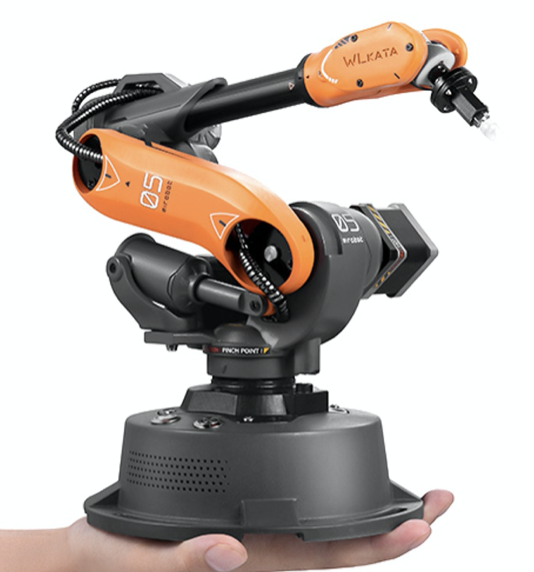
RESEARCH: Mirobot Robot Arm
Mirobot is a miniature highly accurate robotic arm that was launched via the KickStarter in 2020. As the industrial robots such as KUKA is normally not accessible to most people, Mirobot fill the need for a replica for personal use for education and development.
More information to follow as the project backers are starting to receive the robots.
RESEARCH: Interbotix PincherX 150 Robot Arm
Interbotix PincherX 150 Robot Arm
Uses 8x Dynamixel XL430-W250-T to achieve 5 DOF + 360 degrees of rotation.
45cm reach (90cm total span) with 5mm accuracy
RSO support
https://www.trossenrobotics.com/pincherx-150-robot-arm.aspx
Dynamixel XL430-W250-T Smart Servo Motor
Offer high resolution of 4096 positions and user definable PID parameters
Temperature monitoring, positional feedback, as well as voltage levels, load, and compliance settings are user accessible as well
https://www.trossenrobotics.com/dynamixel-xl430-w250-t.aspx
Related resources
Ubiquity – VM image + Rpi image
https://downloads.ubiquityrobotics.com/
Install ROS on Ubuntu – using Robotis script + Install on Raspbian Jessie
https://acslaboratory.github.io/ros/kinetic-ros-installation-guide/
GitHub - X-Series - ROS Stack
https://github.com/Interbotix/interbotix_ros_arms
Github - PhantomX Pincher Mk3 Arm
RESEARCH: Annin Robotics AR2 & AR3 6 axis Robot Arm
Main Website - anninrobotics.com
Blog - https://www.anninrobotics.com/blog
Forum - https://www.anninrobotics.com/forum
Tutorials - https://www.anninrobotics.com/tutorials
Download & Manuals - https://www.anninrobotics.com/downloads
Robot Kits - https://www.anninrobotics.com/robot-kits
RESEARCH: ESP8266 & ESP32
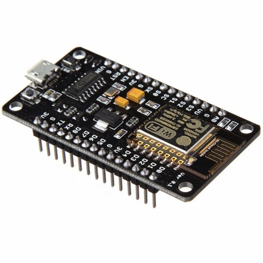
For the maker community as of 2019, ESP8266 and ESP32 are most commonly used in place of the Arduino. The main reason for the popularity includes small form factor, cheaper price point, support for Arduino IDE for programming, and built in Wifi. These models are produced by the Espressif Systems in Shanghai, China.
ESP8266 - Released in 2014 - https://en.wikipedia.org/wiki/ESP8266
CPU: 80 MHz (default) or 160 MHz (single core 32-bit) processor
Memory: 32 KiB (80 KiB user data)
Input: 16 GPIO pins
Comm: 802.11 wifi
CONS - One of the major drawback is the lack of security - details WIP
ESP32 - Released in 2016 - https://en.wikipedia.org/wiki/ESP32
CPU: 160 or 240 MHz (dual core 32-bit) processor
Memory: 520KiB SRAM
Input: TBD (need to confirm)
Comm: 802.11 b/g/n Wifi; Bluetooth v4.2
CONS - Some of the older codes written for 8266 may not run on the ESP32. However, I would initiate new projects based on the ESP32.
WORK IN PROGRESS BELOW———————————————-
ESP32 vs ESP8266 - Pros and Cons
https://makeradvisor.com/esp32-vs-esp8266/
ESP32 Pinout Ref
https://randomnerdtutorials.com/esp32-pinout-reference-gpios/
ESP8266 Pinout Ref
https://randomnerdtutorials.com/esp8266-pinout-reference-gpios/
Banggood - description
Andy’s blog
http://www.areresearch.net/2018/02/the-all-you-can-possibly-want-esp8266.html#
ESP8266 Deauther 2.0
https://github.com/spacehuhn/esp8266_deauther/blob/master/README.md
https://www.youtube.com/watch?v=elKXLAs3zII
https://github.com/spacehuhn/esp8266_deauther/wiki/Installation#flashing-the-firmware-bin-file


